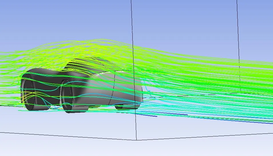
Flow
A low-drag car, simulated in Ansys and then put in a wind tunnel.
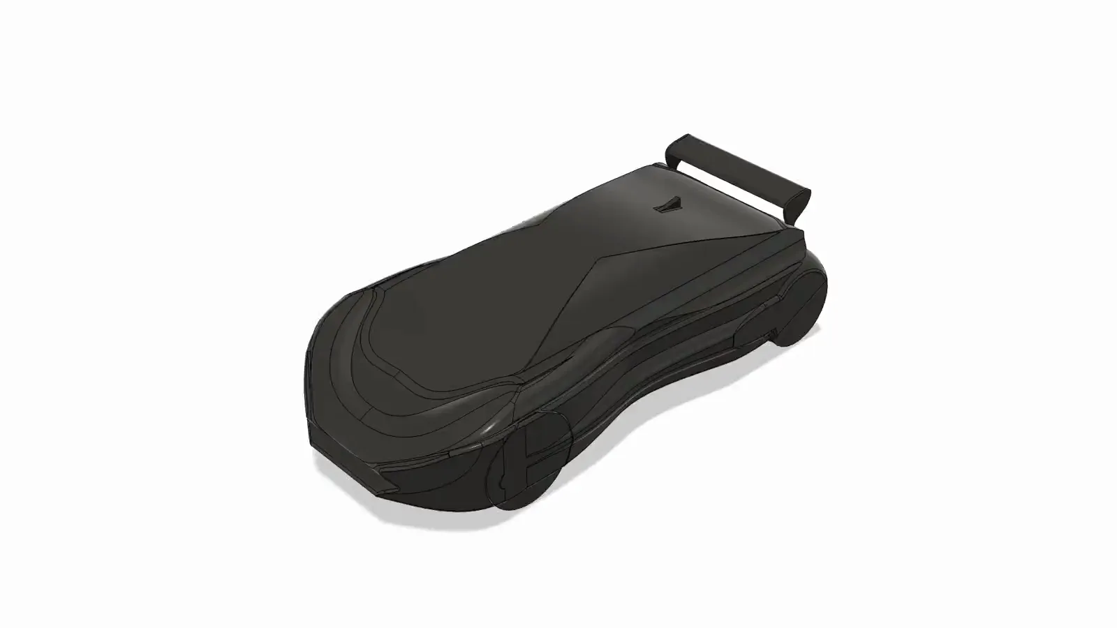
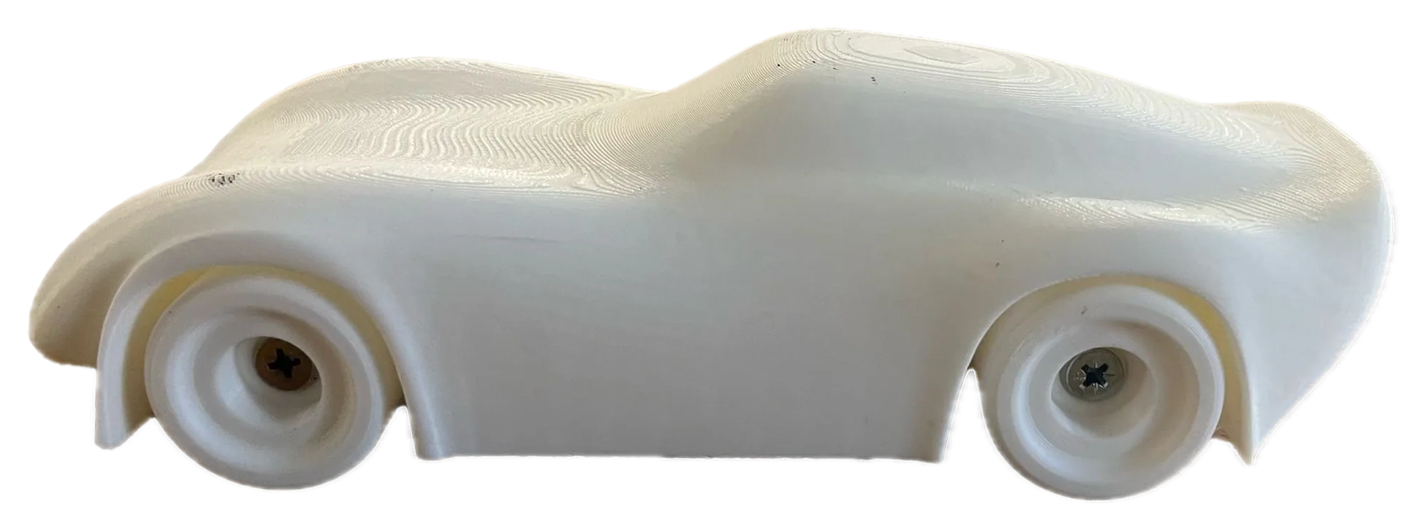
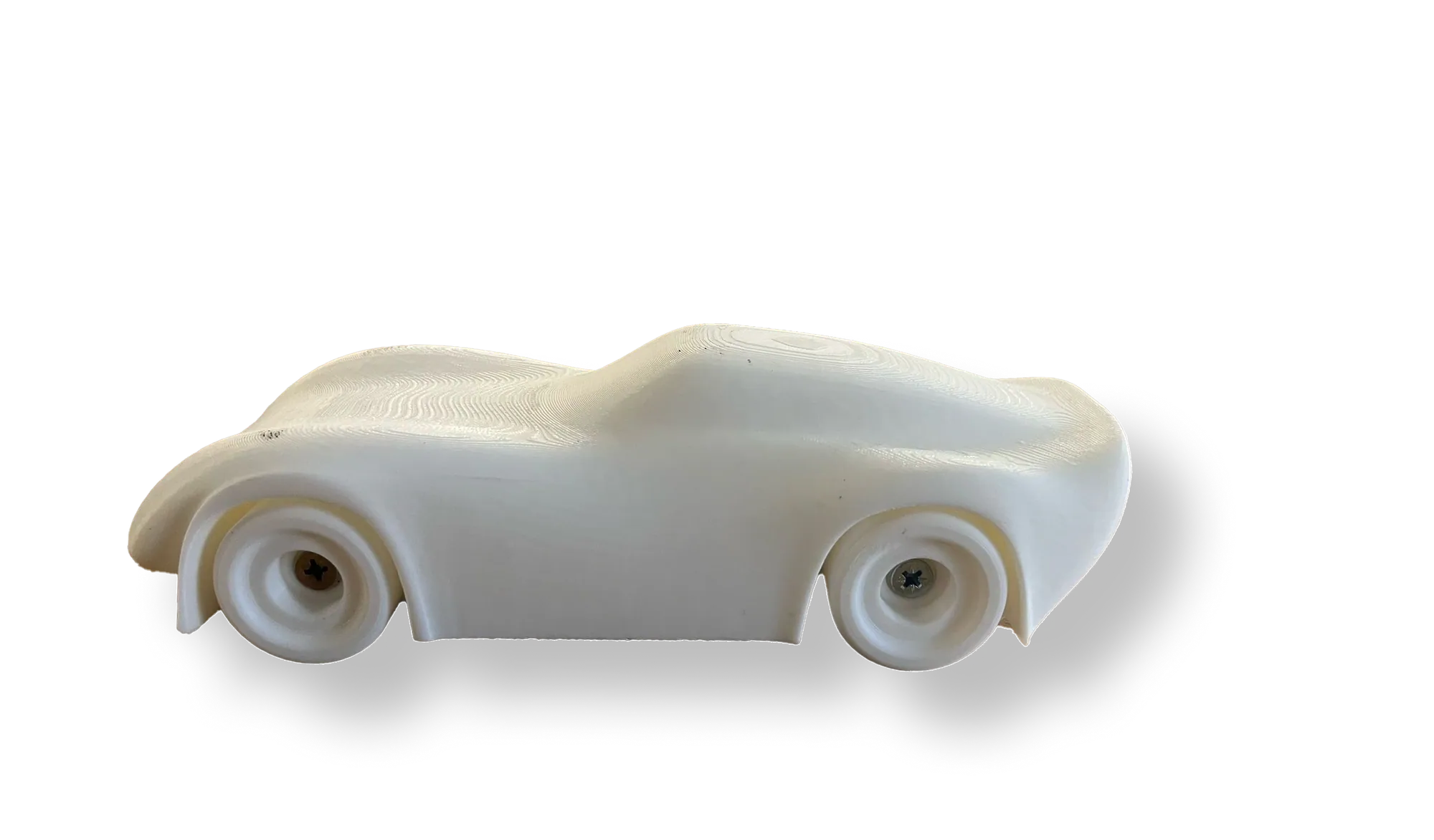
A sports car concept modelled in Ansys Fluent as a half-car with a symmetry plane, then 3D printed at 225 mm and tested in Imperial's T1 wind tunnel to see how far the simulation could be trusted.
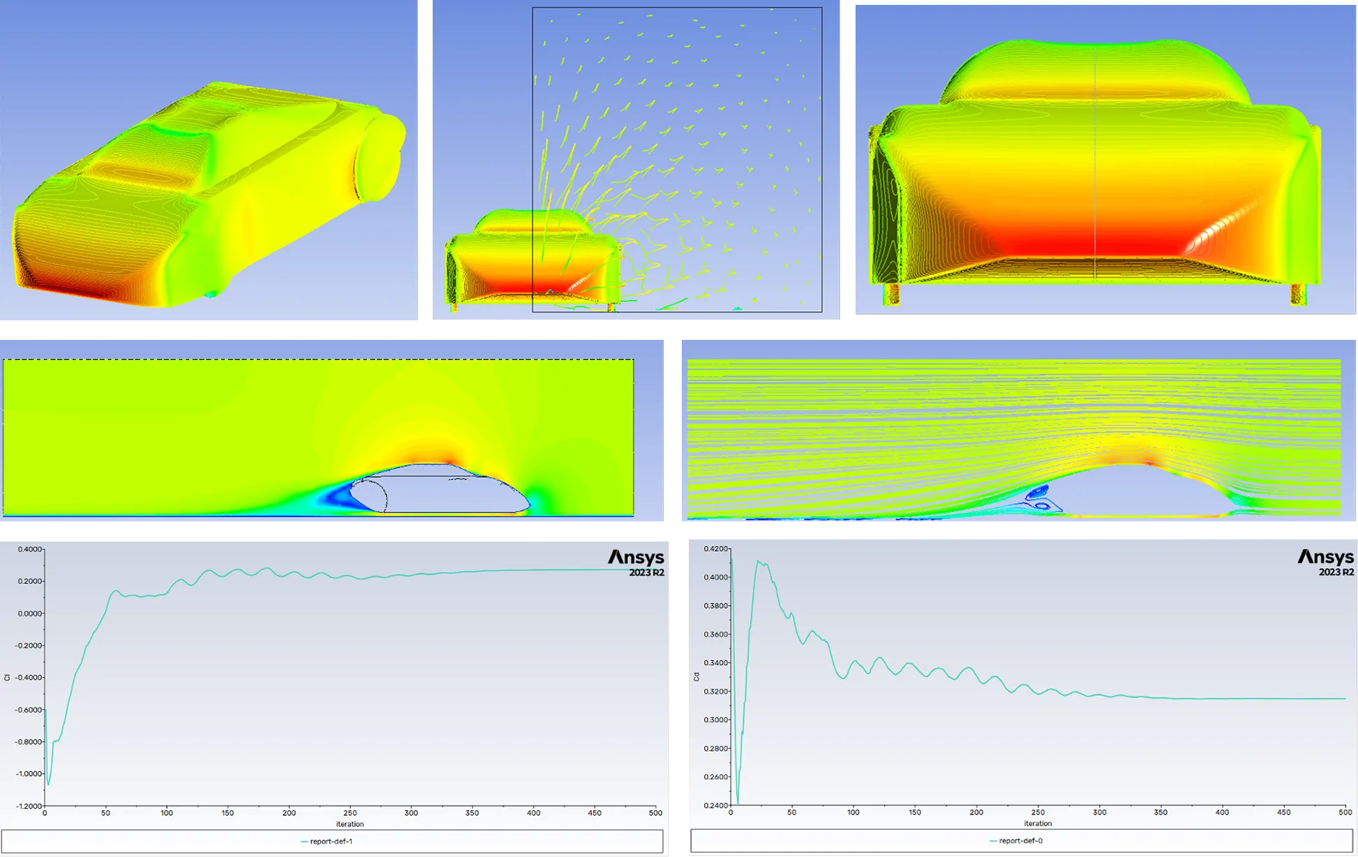
About 563 Pa at stagnation, as the flow meets the body.
Active above 100 km/h, for downforce when it counts.
Smooth wheels and spat covers calm wheel-arch turbulence.
- Brief
- Design a low-drag, high-downforce sports car, then prove it in CFD and a wind tunnel.
- Role
- CFD analysis on my own; printing and tunnel testing as a team.
- Outcome
- Corrected for frontal area, tunnel drag (Cd ≈ 0.25) matched the CFD. Lift didn't: the tunnel showed downforce where CFD predicted lift.
0.25
drag coefficient, CFD
0.30
drag coefficient, tunnel at 30.5 m/s
I got it wrong. I had moved too quickly into CAD and precision, instead of using sketching to think through form and airflow.
- 01
Simulate
Half a car, 2.5 million cells, steady RANS at 30.5 m/s.
- 02
Print
A 225 mm model, printed at an angle for a smoother surface.
- 03
Tunnel
Imperial's T1 tunnel at 18 and 30.5 m/s.
- 04
Compare
Flow patterns matched the tracers. The lift did not, and that became the lesson.